deployable exhibition space
arch564- advanced materials structures, fall 2019prof. harry giles
jun zhou
ANSYS + CESedupack
form inspiration
the span of the pompidou is 157 feet. as shown below, the rotatable joint enables the separation of the compression and tension parts of the vertical structural member.
this causes no bending in the columns and tension bars, allowing for thinner members. this idea contributes to the slim effect.
![]()
this causes no bending in the columns and tension bars, allowing for thinner members. this idea contributes to the slim effect.


material choices
 we took another cue
from the pompidou for the main material and used ductile cast iron.
we took another cue
from the pompidou for the main material and used ductile cast iron.
we were also inspired by this project. we appreciated how the designers were able to puncture the structural member to create a lighter structure, just like in the pompidou.


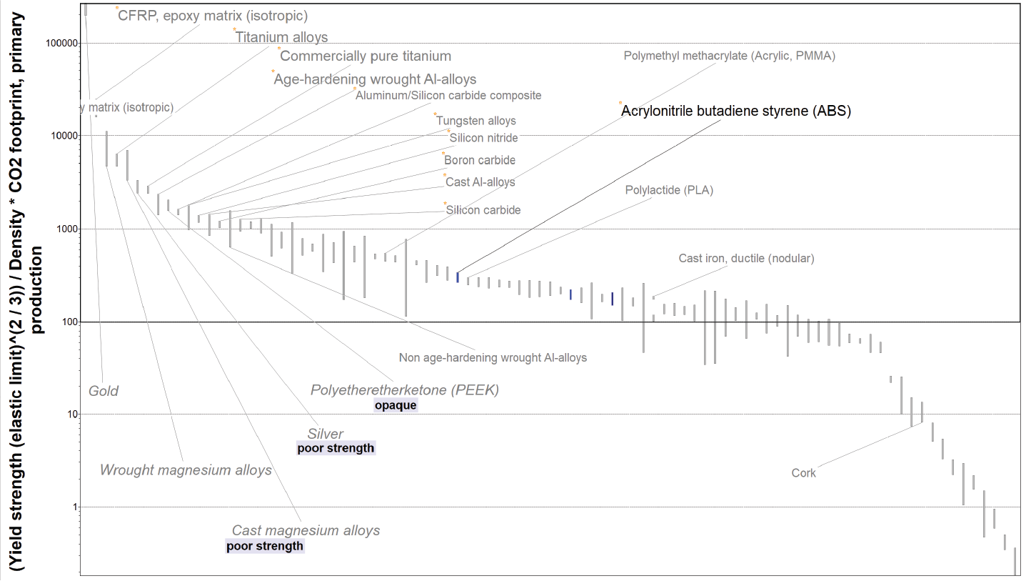


to begin with, we graphed the yield strength2/3/density * co2 primary production footprint. we looked at what was in the top half of the graph and got a better idea about what we were looking for. we also looked at the young’s modulus1/3/density * co2 primary production footprint.
we narrowed down our field by eliminating hard and softwood, steel, and concrete. we also limited our results by creating a limit for durability in industrial environments for only accpetable and excellent ratings1.
however, we found that these graphs were not giving us the full story, so we started by looking at yield strength2/3 vs. density. this gave us lighter, stronger materials. we recognized that cast iron is not a light material, but we decided that the design would benefit from the material. however, we found that cfrp was really high strength and slightly lighter. pmma was also pretty high strength (but comparable for polymers). it passed the durability test and was fairly light.
we then looked at light and stiff materials by graphing young’s modulus1/3 vs. density. we found that cfrp and pmma were both great in these. as expected, cast iron was heavy, but very stiff. this stiffness would prove to be necessary in later stages of the project.
near the end of our project, we tested a different material, age-hardening wrought aluminum, just to see if it was possible to lighten the structure through that material choice. however, the strength and stiffness were much lower and it did not work.
in sum, our main material choices are:
cast iron, ductile (nodular)
cfrp
acrylic (pmma)
bamboo
drawings and images

the joint is comprised of various parts (below). these parts are bolted for easy maintenance and installation.


img. 1
joint undergoes a small stress, so a single-sided node connection is used.
joint undergoes a small stress, so a single-sided node connection is used.
img. 2
cfrp rods are more stressed, causing us to need double-sided nodes
cfrp rods are more stressed, causing us to need double-sided nodes
img. 3
releases the constraint of one direction, which is in line with our calculation assumptions. in this joint, the pillars only undergo axial forces
releases the constraint of one direction, which is in line with our calculation assumptions. in this joint, the pillars only undergo axial forces


mechanical analysis

load 1: d+l(downward)
w = 7.9 * (30+4) = 268.6 lb/ft2
load 2: d+w(upward)
w = 7.9 * (40-4) = 284.4 lb/ft2
our next design step was to check our ansys model. we loaded our model with 300 lb/ft² (downwards). we chose this load to give us a higher safety factor. we then chose one bay of our design as our analysis unit.

from this test, we found a number of problems – for one, we needed something on the cantilever side to cut down on deflections. we decided that we would add an additional column to the other side and work with more cross-bracing.
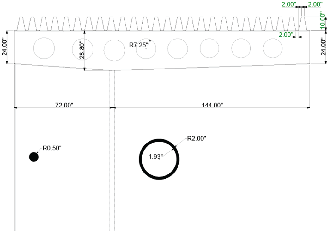
we also decided that we could castellate the beam in order to cut down on the amount of material we were using.
the roof was also an issue. we tried using a thicker flat roof (a 1” pla roof). this did not work. we decided that for the next round we would corrugate and thin the roof to decrease deflections in the roof. we also switched the material to pmma due to its durability.

deformation = 11.589”

stress:
cfrp: 61.74ksi < 79.8ksi
cast iron: 23.979ksi < 35.7ksi
pla: 2.69ksi < 8ksi
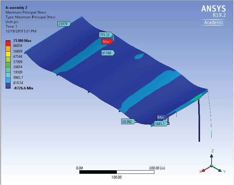
when we ran the ansys model of our newly improved bay, we found that it performed much better. the stresses were quite low and the deformations were far lower than in the previous run.`
since all of the materials we chose were acceptable in terms of their stresses, we found that the design was controlled by deflection. the largest deformation we found was 0.83 in, which is acceptable. therefore, our structure passes.
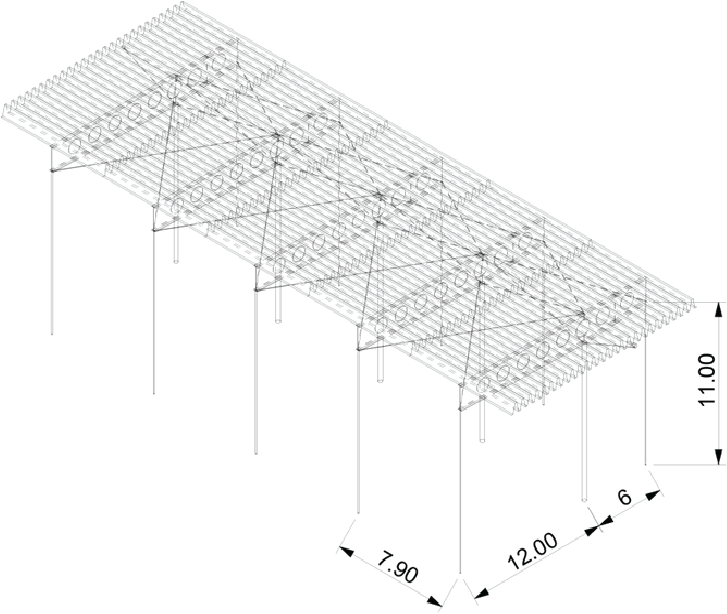
we also looked at an upward load. our original inspiration only had one column and a very large cantilevering beam, which we soon realized would cause issues when load was applied going upwards. so, to combat this, we included a second column, removing the problematic cantilever and pulling down the tip of the beam. the whole beam is simply supported which is safer than the load condition that we put into ansys. we found that the structure is safe under the given load.
in order to tie the bays together, we also included a cross beam that spans through all 5 bays and diagonal cross bracing that ties down the large beam.

deformation < 1”

stress:
cfrp: 3.38ksi < 79.8ksi
cast iron: 3.21ksi < 35.7ksi
pla: 0.83ksi < 8ksi


deformation < 1”
these changes improved the design and allowed for the structure to pass.
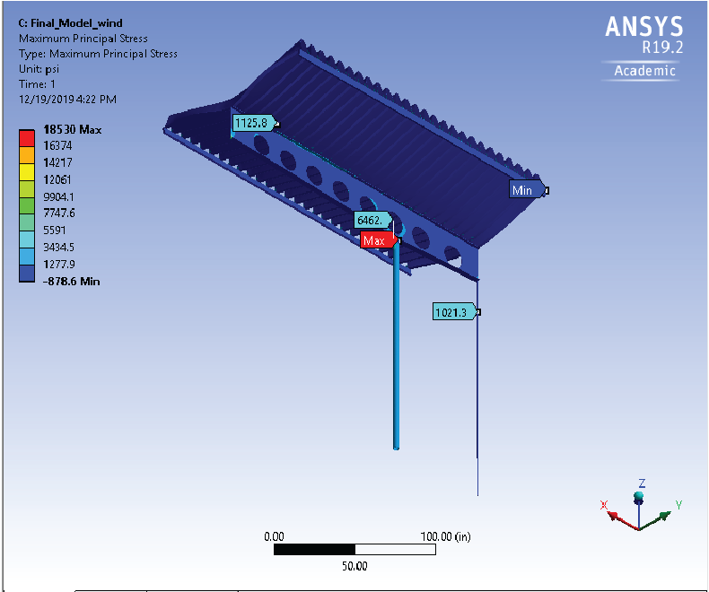
we also checked the wind load, which also passed.
we also checked the wind load, which also passed.
ecoanalysis
we performed an eco analysis on the four materials. we assumed that all materials would be transported 500 mi by ocean freight since it is a sea-side site. we also assumed a product life of 10 years. cast iron, which was the most energy and co2 intensive, was processed through casting and recycled at the end of its life. next, cfrp was processed through compression molding and remanufactured after use. pmma was processed through polymer extrusion and then was reused. finally, bamboo’s production value was included in the material value. at the end of its life, it will be re-manufactured. through the eco-analysis, we found that the critical phase is the material phase.

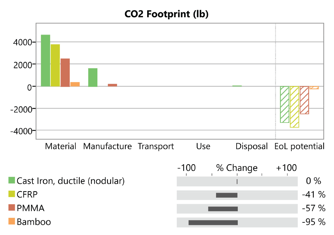

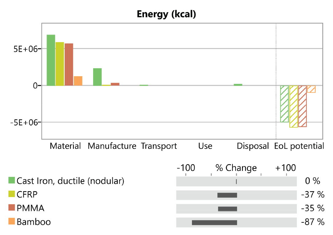
by looking at the same materials in comparison to cast iron, we can understand how much better materials like bamboo are. however, we can look at the materials in comparison to bamboo and undesrstand how much worse the other materials are in comparison.
weight and cost analysis
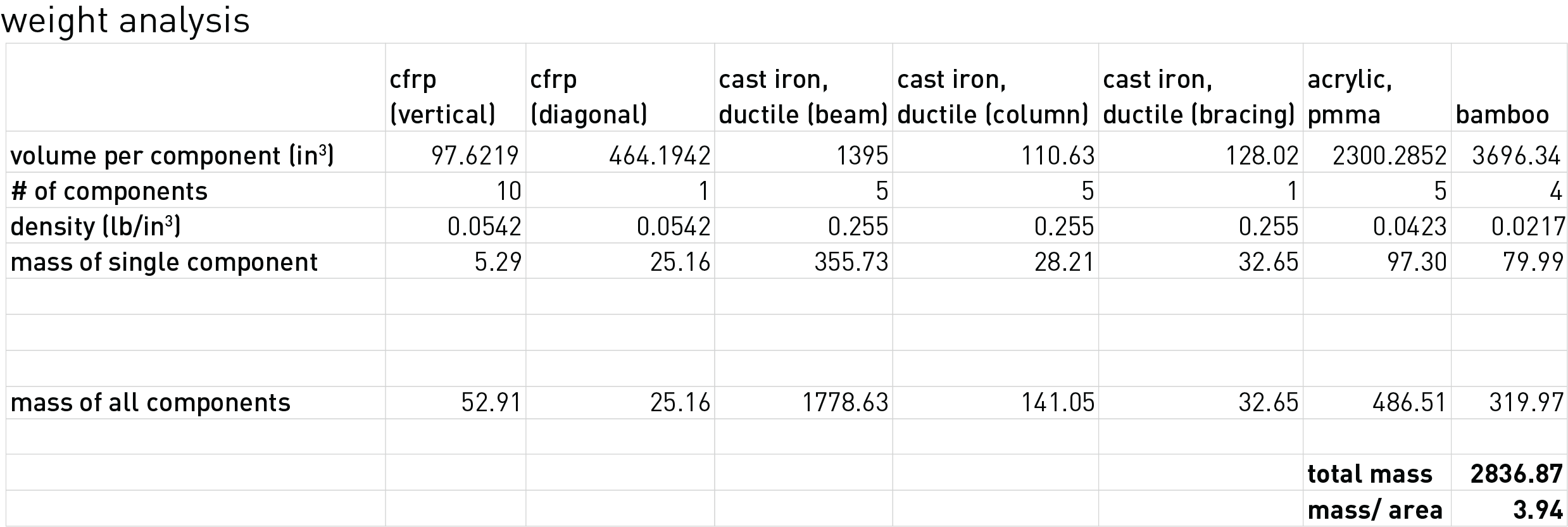
we calculated the weight by first breaking each material down into its use. the next step was finding the volume of a single component and then multiplying the number of components to find the total mass. we used this method because by breaking the weight down in this way, it was easy to see what properties needed to change. we wanted to use bamboo for the roof. this turned out to be way too heavy (our total value was over 5 lb/sqft). this chart proved invaluable becuase we were able to quickly understand that the cast iron beam’s volume needed to decrease to about 700 in³ if we wanted to use bamboo. since that was unreasonable, we tested decreasing the height of the whole structure to 10’. this decreased the values for the vertical members, including the wall, but did not provide enough of a difference to warrant continuing, so we decreased the volume of bamboo needed (by decreasing the thickness).
